
GI 275 Installation Manual⁚ A Comprehensive Guide
Embark on a journey to seamlessly integrate the Garmin GI 275 into your aircraft with our comprehensive installation guide. This resource offers detailed steps for a successful and efficient installation process‚ tailored for pilots and technicians alike.
GI 275 Description and Overview

The Garmin GI 275 is a versatile electronic flight instrument designed as a direct replacement for legacy primary flight instruments. Its lightweight and compact form factor reduces installation time and cost‚ making it an ideal upgrade for various aircraft‚ from piston singles to jets. Approved for installation in over a thousand models‚ the GI 275 enhances the flying experience with modern functionality.
This instrument seamlessly integrates into existing avionics systems‚ offering features like attitude‚ airspeed‚ altitude‚ and vertical speed in a single‚ back-mounted 3-inch gauge. It also supports wireless Bluetooth connectivity for added versatility. The GI 275 is resilient and long-lasting‚ providing pilots with a reliable and user-friendly instrument for improved cockpit awareness and flight management. Its comprehensive capabilities make it a valuable addition to any cockpit‚ ensuring safer and more efficient flights.
STC Applicability
The Garmin GI 275 holds FAA approval for installation in over 1‚000 single-engine and multi-engine aircraft models‚ demonstrating its broad STC applicability. This approval simplifies the upgrade process for numerous aircraft owners seeking to modernize their cockpits. The Approved Model List (AML) for STC SA02658SE‚ GI 275 Part 23 AML STC‚ provides a comprehensive reference for determining aircraft compatibility.
Notably‚ the GI 275’s STC allows for versatile configurations‚ including primary ADI and HSI replacements‚ offering significant flexibility in panel upgrades. Even VFR-only certified aircraft can benefit from a single GI 275‚ consolidating essential flight data into one instrument. Furthermore‚ innovative installations such as integrating two GI 275 units into EASy Flight Decks showcase its adaptability across diverse aviation platforms. This extensive STC coverage underscores the GI 275’s widespread utility and appeal within the aviation community.
System Overview
The Garmin GI 275 is a versatile electronic flight instrument designed as a direct replacement for legacy primary flight instruments. This system integrates attitude‚ airspeed‚ altitude‚ and vertical speed indications into a single‚ compact unit. Its resilience and long-lasting design‚ coupled with a lightweight and compact form factor‚ reduce installation time and costs. The GI 275 also supports wireless Bluetooth connectivity‚ enhancing its versatility and user-friendliness.
The system can function as a primary ADI‚ HSI‚ or MFD‚ offering pilots flexible configuration options. Key components and interfaces allow connectivity to other avionics‚ including autopilots and navigation systems. Proper installation‚ including adherence to ESD precautions‚ is crucial to avoid damage. This overview highlights the GI 275’s capabilities as a modern avionics solution aimed at improving cockpit functionality and pilot experience.
Model Specifics
The GI 275 comes in various models tailored to specific aircraft and functional requirements. Distinctions between models include capabilities such as primary attitude indicator (ADI)‚ horizontal situation indicator (HSI)‚ or multi-function display (MFD). Some models support EIS functionality‚ allowing for engine monitoring. Configuration options are crucial‚ including airspeed markings and units (mph or kts). These specifics must be programmed during installation to match aircraft parameters.
Model selection depends on the intended use‚ panel configuration‚ and integration with existing avionics. Certified aircraft‚ even VFR-only‚ can benefit from a single GI-275 providing essential flight data. Understanding model-specific installation requirements ensures optimal performance. Each model may have unique interface capabilities‚ affecting integration with autopilots or other systems.
GI 275 Functions
The GI 275 is a versatile instrument offering a range of functions dependent on its configuration. As a primary ADI‚ it displays attitude‚ airspeed‚ altitude‚ and vertical speed. When configured as an HSI‚ it provides navigation information and course guidance. As an EIS‚ it monitors engine parameters. The GI 275 calculates True Airspeed (TAS)‚ though display availability might vary.
The instrument integrates with various systems‚ including OAT probes for TAS calculations. It supports wireless Bluetooth connectivity. Pilots can display essential flight data‚ enhancing situational awareness. Configuration during installation dictates available functions. The GI 275 can replace legacy instruments‚ modernizing the cockpit. Functionality extends to autopilot integration‚ but manual AHRS/ADC switching may be limited with certain autopilots.
Equipment Overview
The GI 275 is designed to directly replace legacy primary flight instruments‚ featuring a compact and lightweight design. The core unit includes the display screen and internal processing components. Installation requires specific wiring harnesses and connectors‚ detailed in the installation manual. Optional sensors‚ such as OAT probes‚ enhance functionality.
The GI 275 installation may require additional equipment‚ such as mounting brackets. The complete installation package contains aircraft-specific airspeed markings. The unit’s resilience ensures long-lasting performance. Bluetooth connectivity adds to its versatility. The GI 275 EIS Quick Kit simplifies EIS installation‚ offering a base harness and sensor add-ons. Proper handling is crucial to prevent electrostatic discharge (ESD) damage during installation.
Display Features
The GI 275 boasts a vibrant display‚ providing pilots with critical flight information at a glance. It can show attitude‚ airspeed‚ altitude‚ and vertical speed. The display is customizable‚ allowing pilots to prioritize essential data. The GI 275’s screen is protected by a plastic film during shipping and installation to prevent scratches.
The unit’s display settings can be configured to adapt to various lighting conditions for optimal visibility. The GI 275 is capable of displaying True Airspeed (TAS)‚ enhancing situational awareness. The display is user-friendly and designed to improve the overall flying experience. The display provides comprehensive engine information when configured as an EIS. These features are all part of a powerful electronic flight instrument.

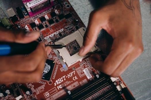
Installation Procedures
Proper installation is crucial for the GI 275. This section provides detailed instructions for physically mounting the unit‚ connecting power‚ and interfacing with other avionics systems. Follow these steps carefully to ensure correct operation.
Mounting the GI 275
Carefully position the GI 275 onto the mounted bracket‚ ensuring it is perfectly level for optimal performance. Securely fasten the device to the bracket using the appropriate hardware‚ following detailed instructions provided in this section. Diagrams and illustrations are included for clarity.
Before beginning the physical installation‚ ensure the selected mounting location meets all clearance requirements and provides adequate ventilation. Consider the accessibility of connections and the overall impact on cockpit ergonomics. The GI 275 boasts a lightweight and compact design‚ simplifying the mounting process and minimizing installation time and cost.
Verify the mounting bracket is securely attached to the aircraft structure. Double-check all connections and hardware for proper torque. The GI 275 has a plastic film on the display glass to protect from scratches during shipping and installation. Remember to remove this after completing the mounting process.
Following these steps ensures a stable and reliable foundation for your GI 275‚ contributing to its longevity and accurate performance.
Connecting Power
This section provides detailed instructions for connecting the GI 275 to the aircraft’s power supply‚ ensuring a stable and reliable source of energy. Safety precautions are clearly stated to prevent damage to the unit and ensure personnel safety.
Before commencing any electrical work‚ disconnect the aircraft’s master switch and any relevant circuit breakers to isolate the power system. Identify the appropriate power and ground wires according to the wiring diagrams provided in the installation manual. Use the correct crimp tools and connectors for secure and reliable connections.
Ensure the power source meets the GI 275’s voltage and current requirements. Employ proper wiring techniques‚ including correct wire gauges and insulation‚ to prevent shorts or interference. After completing the connections‚ carefully inspect all wiring for proper routing and secure terminations.
Reconnect the aircraft’s master switch and circuit breakers‚ and verify the GI 275 powers on correctly. Perform a functional test to confirm proper operation before proceeding to the next step.
Connecting to Other Avionics
This section details the procedures for connecting the GI 275 to other avionics systems within the aircraft‚ enabling seamless data sharing and enhanced functionality. Interfacing with devices like autopilots‚ GPS units‚ and engine monitoring systems requires careful attention to detail and adherence to established protocols.
Prior to beginning any connections‚ consult the wiring diagrams for both the GI 275 and the target avionics. Identify the appropriate data ports and wiring configurations for each device. Ensure compatibility between the GI 275 and the connected avionics to avoid data conflicts or system malfunctions.
Utilize shielded cables and proper grounding techniques to minimize interference and ensure data integrity. Double-check all connections for secure terminations and proper pin assignments. After completing the wiring‚ thoroughly test the interfaces to verify correct data transmission and system integration.
Pay close attention to any specific configuration settings required for each connected device. Refer to the respective manuals for detailed instructions on setting up data protocols‚ baud rates‚ and other communication parameters.

Configuration and Setup
After installation‚ configure the GI 275 to match your aircraft’s specifications. This crucial step ensures optimal performance and accurate data display. Proper setup is vital for safe and efficient flight operations.
Airframe-Specific Configuration
Tailoring the GI 275 to your specific airframe is paramount for accurate performance. Begin by consulting the airframe-specific configuration data within the GI 275 installation manual. This section provides crucial parameters that must be precisely configured to match your aircraft’s unique characteristics. Inputting correct V-speeds‚ as highlighted in online discussions‚ is essential for flight safety and operational efficiency.
Carefully review tables such as ‘Table 5-20 Taws Airframe-Specific Configuration Data’ in the manual to ensure all settings align with your aircraft model. This includes airspeed markings and other critical flight parameters. The manual also specifies switch requirements that must be adhered to for proper functionality. Furthermore‚ confirm compatibility with other avionics systems‚ such as autopilots‚ noting any limitations‚ like the manual switching of AHRS or ADC sensors when interfaced with a GFC 500 Autopilot. Accurate configuration guarantees the GI 275 functions seamlessly within your cockpit environment‚ providing reliable and precise flight information.
EIS Configuration
Configuring the Engine Indication System (EIS) features of the GI 275 involves meticulous attention to detail for accurate engine monitoring. Refer to the ‘EIS Configuration ⎼ Engine’ section‚ such as ‘Table 5-21’‚ within the installation manual for detailed guidance. Input parameters like fuel flow K-factor‚ referencing tables such as ‘Table 5-23‚’ to ensure precise fuel consumption readings. Consider utilizing the Garmin GI 275 EIS Quick Kit to streamline sensor connections and simplify the installation process.
Ensure all sensor inputs are correctly wired and calibrated according to the manual’s instructions. Verify compatibility with existing engine sensors and make necessary adjustments. Properly configured EIS provides real-time engine data‚ enhancing situational awareness and enabling proactive maintenance. Remember to consult with authorized dealers for assistance‚ particularly when dealing with critical sensors. Precise EIS configuration optimizes engine performance monitoring‚ contributing to safer and more efficient flights.