
Circuit track manuals are vital resources, detailing DIY electronics, components, and projects – including power sources․ They spread knowledge, aiding in design and troubleshooting․
What is a Circuit Track Manual?
A circuit track manual serves as a comprehensive guide for understanding, designing, and maintaining various circuit systems․ These manuals, often incorporating videos and diagrams, disseminate knowledge about electronics, components, and projects․ They cover PCB design, fabrication techniques – both manual and CAD-based – and delve into the intricacies of track monitoring and fault detection․ Essentially, it’s a resource for DIY enthusiasts and professionals alike, offering insights into building and troubleshooting complex electronic setups․
Importance of a Detailed Manual
A detailed manual is paramount for successful circuit track implementation․ It minimizes errors during PCB layout and etching, ensuring signal integrity and reducing noise․ Crucially, it aids in effective fault detection and repair, preventing costly downtime․ For racing circuits, a manual guarantees adherence to stringent safety requirements and optimal sector design, ultimately enhancing driver skill testing and precision․

Understanding Track Circuit Technology
Track circuit technology relies on basic principles for monitoring sections, utilizing DC or AC systems with specific components for reliable condition assessment․
Basic Principles of Track Circuits
Track circuits fundamentally operate by detecting the presence or absence of a train on a specific section of railway track․ This is achieved by passing a constant current through the rails; a train’s wheels and axles short-circuit the current to ground, signaling its presence․
The core principle involves a power source, track sections acting as a return path, and a relay that detects current changes․ Absence of a short indicates a clear track, maintaining the relay’s energized state, while a short de-energizes it, triggering signals or safety systems․
Components of a Typical Track Circuit
A typical track circuit comprises several key components working in unison․ These include a track feed, supplying the alternating or direct current to the rails; a relay, responsible for detecting current variations; and bonding, ensuring electrical continuity․
Further components are insulating joints, isolating track sections; and filter units, minimizing interference․ These elements collectively form a robust system for reliable train detection and signaling, crucial for railway safety and operational efficiency․
Types of Track Circuits: DC & AC
Track circuits broadly fall into two categories: Direct Current (DC) and Alternating Current (AC)․ DC track circuits utilize a constant voltage, offering simplicity but susceptibility to stray currents․ AC circuits, conversely, employ alternating voltage, providing greater immunity to interference․
The choice between DC and AC depends on specific application requirements, considering factors like track length, signaling needs, and potential sources of electrical noise for optimal performance․

Manual PCB Design & Fabrication
Manual PCB design involves layout techniques and etching processes, crucial for creating printed circuit boards without automated software assistance, demanding precision․
Manual PCB Layout Techniques
Manual PCB layout relies on transferring a circuit schematic onto a copper-clad board․ This involves carefully planning component placement for optimal signal flow and minimal track lengths․ Techniques include using transfer paper, photoresist methods, or direct toner transfer․ Accuracy is paramount, requiring a steady hand and attention to detail to avoid shorts or open circuits․ Proper planning minimizes the need for extensive rework, ensuring a functional and reliable board․
Component Placement Considerations
Effective component placement is crucial for PCB functionality․ Prioritize grouping components based on their circuit roles, minimizing track lengths and signal interference․ Consider thermal dissipation; heat-generating components need adequate spacing․ Decoupling capacitors should be placed close to IC power pins․ Orientation matters – align polarized components consistently․ Strategic placement simplifies routing and improves overall circuit performance and reliability․
Manual PCB Etching Processes
Manual PCB etching involves transferring a circuit pattern onto a copper-clad board․ Begin by applying a photosensitive resist, exposing it to UV light through a mask, and developing the unexposed areas․ Immerse the board in an etchant solution (like ferric chloride) to remove unprotected copper․ Thorough rinsing and resist removal complete the process, yielding a custom PCB․

CAD-Based Circuit Track Design
CAD software revolutionizes PCB design, enabling precise track routing and component placement․ Generating Gerber files facilitates manufacturing, streamlining the creation of complex circuits efficiently․
PCB design software is essential for modern circuit track creation, moving beyond manual methods․ These tools allow designers to visualize, layout, and analyze printed circuit boards with precision․ Software packages offer features like schematic capture, automated track routing, and component library management․ They significantly reduce design time and improve accuracy, facilitating complex designs․ Utilizing CAD streamlines the process, from initial concept to generating manufacturing files like Gerber files, ensuring efficient production of electronic circuits․
Using CAD for Track Routing
CAD software automates track routing, a critical step in PCB design․ Designers define constraints – width, spacing, layers – and the software intelligently connects components․ This minimizes design errors and optimizes signal integrity․ Advanced features include differential pair routing and impedance control․ CAD tools also perform design rule checks, ensuring manufacturability․ Efficient routing is vital for reliable circuit performance, and CAD significantly accelerates this complex process, improving overall design quality․
Generating Gerber Files
Gerber files are the standard output from PCB design software, essential for manufacturing․ They contain instructions for each layer – copper traces, solder mask, silkscreen – used by fabrication houses․ Accurate Gerber generation is crucial; errors lead to board defects․ These files define drill locations, pad sizes, and component placement․ Proper file creation ensures the physical board matches the design, facilitating a smooth production process and reliable circuit functionality․
Designing Racing Circuit Tracks
Racing track design focuses on elements like high-speed corners, straights, and elevation changes to test driver skill and create exciting overtaking opportunities․
Key Elements of a Racing Track Layout
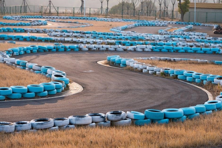
A successful racing circuit demands a carefully orchestrated layout․ Key elements include challenging high-speed corners demanding precision, and strategically placed hairpins forcing drivers to slow considerably․ Long straights provide overtaking opportunities, while chicanes test braking and handling․ Elevation changes add complexity and visual appeal, creating a beautiful, demanding symphony of turns․
High-Speed Corners and Hairpins
Effective track design balances thrilling high-speed corners with technically demanding hairpins․ Corners test a driver’s skill and precision, requiring optimal lines and braking points․ Hairpins dramatically reduce speed, creating overtaking zones and emphasizing braking prowess․ A harmonious blend of both elements is crucial for a captivating and challenging circuit․
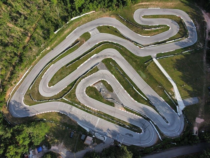
Straights, Chicanes, and Elevation Changes
Strategic track layouts incorporate long straights for high-speed runs, punctuated by challenging chicanes demanding precise control and braking․ Elevation changes add complexity, testing driver adaptability and vehicle balance․ These elements create a “symphony of turns,” maximizing excitement and providing opportunities for overtaking maneuvers, resulting in a dynamic racing experience․
Track Monitoring & Condition Assessment
Monitoring methods utilizing track circuits are crucial for assessing track section condition, enabling fault detection, and ensuring reliable performance through consistent troubleshooting procedures․
Methods for Monitoring Track Sections
Effective track section monitoring relies on diverse techniques, broadly categorized into those employing track circuits and alternative approaches․ Track circuits themselves provide continuous electrical assessment, detecting occupancy or faults․ Beyond this, visual inspections are essential for identifying physical damage or wear․ Regular testing of components, like PCB connections, ensures functionality․ Data logging and analysis of circuit performance over time reveal potential degradation, enabling proactive maintenance and preventing unexpected failures, ultimately maximizing system reliability and safety․
Using Track Circuits for Condition Monitoring
Track circuits excel at condition monitoring by constantly evaluating electrical characteristics․ Changes in impedance, signal strength, or frequency indicate potential issues like broken rails, insulation faults, or wheel defects․ Automated systems analyze these signals, triggering alerts for immediate investigation․ This proactive approach minimizes downtime and enhances safety․ Integrating data logging provides historical trends, predicting failures before they occur, and optimizing maintenance schedules for maximum efficiency and reliability of the entire system․
Fault Detection and Troubleshooting
Effective troubleshooting begins with systematic testing of track circuit components․ Common failures include open circuits due to broken connections, short circuits from insulation breakdown, and component degradation․ Utilizing multimeters and oscilloscopes to verify voltage, current, and signal integrity is crucial․ Detailed manuals provide schematics and diagnostic procedures, guiding technicians through isolation and repair․ Regular inspection and preventative maintenance significantly reduce the frequency of unexpected failures and ensure operational reliability․
Logic Pro Track Stacks
Track Stacks in Logic Pro allow combining tracks with diverse subtrack types, enhancing organization and workflow for complex projects and creative sound design․
Creating Track Stacks
To initiate a Track Stack within Logic Pro, simply select the desired tracks located in the Tracks area․ This selection forms the foundation of your stack․ These stacks can then accommodate a versatile array of track types as subtracks, offering immense flexibility․ This feature streamlines project organization, allowing for efficient grouping and manipulation of related audio or MIDI elements․ It’s a core technique for managing complex arrangements and fostering a more intuitive workflow, ultimately boosting creative potential․
Subtrack Types and Combinations
Track Stacks demonstrate remarkable versatility, seamlessly integrating any combination of track types as subtracks․ This includes audio tracks, MIDI tracks, instrument tracks, and even other Track Stacks, creating nested hierarchies․ Such flexibility empowers users to construct intricate arrangements and signal chains․ This allows for complex routing and processing, fostering creative sound design and efficient project organization within Logic Pro’s environment, maximizing workflow potential․
Benefits of Using Track Stacks
Track Stacks offer substantial organizational advantages, consolidating multiple tracks into a single, manageable unit․ This simplifies mixing and automation, reducing clutter and improving workflow efficiency․ They facilitate complex routing and processing, enabling sophisticated sound design․ Furthermore, Track Stacks promote creative experimentation and allow for easy duplication and manipulation of entire track groups, streamlining project development․

Formula 1 Track Design Considerations
F1 track design prioritizes safety, sector layouts, and overtaking zones, following Hermann Tilke’s process․ Construction costs since 1999 reach approximately 270 million USD․
Hermann Tilke’s Design Process
Hermann Tilke’s approach to Formula 1 track design is a meticulous process, focusing on creating challenging yet safe circuits․ It involves careful consideration of high-speed corners, hairpins, straights, and elevation changes․ The goal is a harmonious blend of turns testing driver skill and precision․ Safety is paramount, dictating run-off areas and barrier placement․ Sector design and strategic overtaking zones are also crucial elements, aiming to enhance race excitement and competitive opportunities for drivers throughout the circuit․
Safety Requirements for F1 Tracks
F1 track safety is rigorously enforced, demanding extensive run-off areas beyond track edges to mitigate impacts․ High-integrity barrier systems, like Tecpro and tire walls, absorb energy during collisions․ Medical facilities must meet stringent standards, ensuring rapid response to incidents․ Track surfaces require precise specifications for grip and drainage․ Regular inspections and FIA homologation are vital, guaranteeing circuits adhere to the highest safety protocols, protecting drivers and marshals alike․
Sector Design and Overtaking Zones
Effective sector design balances speed and challenge, creating distinct characteristics within a lap․ Overtaking zones are strategically placed, utilizing long straights followed by braking areas, encouraging wheel-to-wheel racing․ Designers consider track width, banking, and DRS zones to facilitate passing maneuvers․ A “beautiful symphony of turns” tests driver skill, while varied layouts promote exciting competition and strategic diversity throughout the race․

Advanced Circuit Analysis Techniques
Advanced analysis focuses on signal integrity, noise reduction, and impedance control for optimal track performance․ Thermal management is also crucial for reliability․
Signal Integrity and Noise Reduction
Maintaining signal integrity is paramount in circuit track design, demanding careful attention to layout and component placement․ Minimizing noise requires strategic grounding techniques and shielding to prevent unwanted interference․ Proper impedance control ensures efficient signal transmission, reducing reflections and distortions․ Addressing these factors guarantees reliable performance and accurate data transfer within the circuit, crucial for complex electronic systems and DIY projects․
Impedance Control in Track Design
Impedance control is critical for high-speed circuit tracks, ensuring signals travel efficiently with minimal reflection․ Achieving this requires precise track width and spacing, alongside controlled dielectric materials․ Maintaining consistent impedance throughout the circuit prevents signal distortion and maximizes data transfer rates․ Careful PCB design, utilizing CAD software, is essential for implementing effective impedance matching techniques for optimal performance․
Thermal Management Considerations
Thermal management is paramount in circuit track design, preventing overheating and ensuring reliability․ Components generate heat, and proper dissipation is crucial․ Techniques include utilizing thermal vias to conduct heat away from components, employing heat sinks, and optimizing component placement for airflow․ Careful PCB layout and material selection contribute to effective thermal performance, extending the lifespan of the circuit․

Emerging Technologies in Circuit Tracks
AI integration, like ChatGPT, offers innovative circuit design solutions․ Voice and image inputs, alongside GPT-4, are revolutionizing creative processes and accessibility․
AI-Powered Circuit Design (ChatGPT Integration)
ChatGPT’s broad availability democratizes AI tools for circuit track design, benefiting over 100 million users globally․ This conversational model assists with follow-up questions and acknowledges errors, enhancing the design process․ It’s core to making AI accessible, fostering innovation in electronics and related DIY projects․ The integration promises creative solutions and streamlined workflows, leveraging AI’s capabilities for complex circuit layouts and troubleshooting, ultimately accelerating development and knowledge sharing within the community․
Voice and Image Input for Circuit Creation
New voice and image capabilities within ChatGPT offer intuitive interfaces for circuit track design․ Users can now engage in voice conversations or visually demonstrate ideas to ChatGPT, streamlining the creative process․ This innovative approach bypasses traditional input methods, allowing for a more natural and efficient exploration of circuit layouts and component arrangements, fostering accessibility and accelerating prototyping for DIY electronics enthusiasts and professionals alike․
GPT-4 for Creative Circuit Solutions
GPT-4 represents a significant leap in creative collaboration for circuit track design․ More imaginative and resourceful than its predecessors, GPT-4 can assist in generating novel solutions to complex circuit challenges․ It excels at answering follow-up questions and acknowledging errors, facilitating an iterative design process․ This advanced model empowers users to explore unconventional approaches and optimize circuit performance effectively․
Maintenance and Repair of Circuit Tracks
Regular inspections are crucial for identifying common failures․ Effective repair techniques and adherence to best practices ensure longevity and optimal performance of circuit tracks․
Regular Inspection Procedures
Consistent monitoring of track sections is paramount․ Visual checks for physical damage, like cracks or corrosion, should be frequent․ Electrical tests, utilizing track circuits, verify continuity and identify potential faults․ Documenting inspection dates and findings creates a valuable history․ This proactive approach minimizes downtime and prevents catastrophic failures, ensuring reliable operation and extending the lifespan of the entire system․ Prioritize safety during all inspection activities․
Common Track Circuit Failures
Frequent issues include insulation breakdown, leading to unwanted shunts․ Component failures, such as relay or diode malfunctions, disrupt signal paths․ Track joint resistance increases over time, causing intermittent detection․ Environmental factors – moisture and corrosion – accelerate degradation․ Proper grounding is crucial; poor grounding introduces noise and false readings․ Regular maintenance and prompt repair mitigate these common problems, ensuring system reliability․
Repair Techniques and Best Practices
Effective repair starts with precise fault location using testing equipment․ Clean corroded connections with appropriate solvents and re-solder carefully․ Replace faulty components with exact equivalents, ensuring correct polarity․ Insulate exposed conductors to prevent future shorts․ Document all repairs thoroughly for future reference․ Prioritize preventative maintenance – regular inspections minimize downtime and extend the lifespan of the circuit track system․
Cost Analysis of Circuit Track Construction
Building F1 circuits can exceed $270 million since 1999․ Costs depend on factors like high-speed corners, elevation, and safety requirements․
Estimated Costs for Building F1 Circuits
Constructing a Formula 1 track represents a substantial financial undertaking, with costs escalating significantly since 1999․ Estimates reveal expenses frequently surpass $270 million, influenced by numerous variables․ These include the complexity of the layout – incorporating high-speed corners, challenging hairpins, and strategically placed chicanes․ Elevation changes also contribute to increased costs, alongside stringent safety requirements mandated by motorsport governing bodies․ Land acquisition, infrastructure development, and ongoing maintenance further inflate the overall investment․
Factors Influencing Track Construction Costs
Several key elements dramatically impact the financial burden of building racing circuits․ High-speed corners, demanding hairpins, lengthy straights, and intricate chicanes all require substantial engineering and construction․ Elevation changes add complexity and expense; Safety infrastructure, including run-off areas and barrier systems, is paramount․ Land acquisition costs, labor rates, and material prices also significantly contribute to the overall project budget, demanding careful resource allocation․
Budgeting and Resource Allocation
Effective budgeting is crucial for successful circuit construction, with F1 tracks costing upwards of 270 million USD since 1999․ Detailed cost estimation must encompass land, materials, labor, and safety features․ Resource allocation requires prioritizing essential elements like track layout, run-off areas, and medical facilities․ Contingency planning for unforeseen expenses is vital, ensuring project completion within financial constraints․